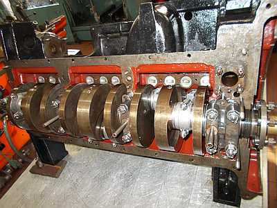
The motor is a straight six cylinder, side camshaft and hanging valves. The block and head is cast iron, all covers aluminium. So far pretty standard. Interestingly the crankshaft is round stock without counterbalances, but with a tilger to eliminate rotational frequencies at the front.
There are some parts missing: The valve head cover. I do have two from the M67 which is 50mm shorter. Pistons are missing as well as the valve rockers with their base. I do have some from the M67, but they are do not fit, but at least a basis for recasting new ones. The camshaft has deep rust holes so I need a new one. The motor must have been open for quite a while: Deep rust on the sealing surface of the head but good cylinder walls – strange. There are marks on the cylinder walls of the pinston pins which might have moved out of the piston once.
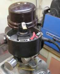
Waterpump (10-12/2014)
This was the first part I took apart and restored it. The housing is aluminium and was extremly seized. I cooled it to -20°C, and heated it up again. Sprayed it with WD40 everday for two weeks. The shaft did not move even when I was trying to rotate it with my biggest 60cm waterpump pliers. So I drilled out the shaft on the lathe. Some whacks with a big hammer and it came apart. One of the cast housing broke, which I had to TIG-weld back together. Cast aluminium is not easy to weld, and the seams are pretty porous. But with some aluminium brazing it was water tight again. I replaced the traditional packing with ceramic seals and made a new shaft out of stainless steel, running now in stainless ball bearings. The car had no heating as standard, but we want to travel and beeing a bit sissy, I want add heating, so I welded another adapter onto the inlet for the heating. This will be below a cover, so nobody will see it, as long as he does not crawl underneath.
Now it still needs the coupling for the dynamo.
Here a picture during assembly with the ceramic seals already in place. This runs very nice and maintenance free.
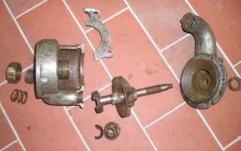
Broken pieces 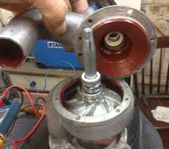
ceramic seals 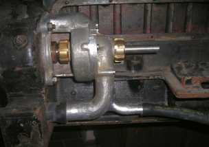
Pump in Place
Zincplating
(here the mounting bracket
of the dynamo regulator)
I guess everybody restoring knows the begging at professional zink plating shops for our small pieces to be plated. You’ll drive back an forth because there is always a special nut you forgot. There are some hints on the internet to do this in house. Here my approach. It works great, speeds up the process and reduces your frustration.
I use a plain plastic container with 2 liters. 2l of water mixed with 600g of „Rohrfrei“ draincleaner containing 30% of NaOH. This gets warm once mixed. There are little aluminium grains inside the draincleaner. They’ll rise up on the surface where they can be skimmed off. Be very careful! That liquid is extremely harmful, acid resistant gloves are mandatory!
Then you mix this with 20grams of zincoxide (from ebay). I use a zinc sheetmetal as anode (+) and hang all my nuts etc. off a bar connected to the kathode (-) of my standard battery charger. It starts bubbling off the pieces. I do turn the pieces form time to time. After approx. 10min depending of the size of the parts they can be rinsed off with clean water. They still look dull grey, which changes to the nice zinc surface once brushed off.
Of course all part have to be absolutely rust free and best polished and degreased prior to zinc coating.
The good thing is that you can even make so tricky things as plating assembled pieces ´.
Motor (1/2015)
Regarding the Motor the inner red sealant paint became soft an sticky so I had the block ice blasted (Not much to see on that photo-It was daylight!). After that I painted the inner surfaces with glyptal paint and the outer surfaces with motor paint. Glyptal requires a 120°C backing for two hours. Fortunately I do have access to an oven big enough. It took 2h to get it to 120°C. Looks nice eh?
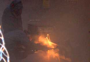
Dry Ice cleaning 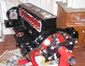
Painted block
The cylinder head has been with another Motor Shop in Hannover, were they plane the sealing surfaces which has a pretty rough surface due to rust. They’ll also rework the valve seats.
I painted similar to the block.
I do not have a valve cover, but there were two covers of a two litre M67 motor coming with the car. They do have the same width, but are over 50mm shorter.
The first cut is quite scary, but required, in order to weld in between two aluminium strips bend accordingly. The welding was, compared to the waterpump, much better. Problem was that the welds do crack even with preheated parts. They cool down too fast. So my wife had to maintain the temperature from the back with a torch. That worked. After sanding them dead smooth and even. I polished them as you’ll see on the before and after photo.
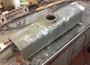
Old Cover cut 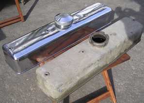
Welded and polished
You still see the weld seams an the strips, because they shine diffently. Any hints welcome. Maybe shot blasting?
The motor block is quite heavy and beyond limits of my existing stand. After a redesign of the stand I preliminary assembled the motor as far as now possible.
I sourced new oil and air filters on the Mann und Hummel webpage, were you can filter by diameters (pretty nice)
I have to turn a holder for the paper oil filter HU711.
The air filter fits like a charm in the old housing which I had to clean, remove the rust and straighten some dents. It now requires new nitro paint. I decided to use nitrocellulose paint, as original throughout the car.
JE SUIS CHARLIE
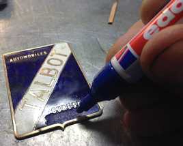
Radiator (2/2015)
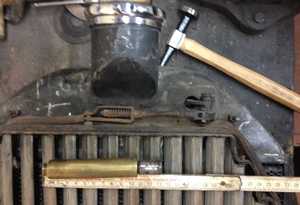
At the Reims bourse d’échange I bought the proper radiator. It has vertical louvres which are actuated by a thermostat inside the radiator.
I mailed the original manufacturer Vernet which produced these shutters for the radiator manufacturer Chausson in 1929. Vernet still producing the so called calorstats. They were very friendly and looked, but did not have anything in the size required (OD 21mm- see the little hole on the phote left).
So the actuator was not working anymore. First I tried to find a replacement part. The Citroen C6 has a similar actuator. But even there I could not find a part. So I have to rework the existing.
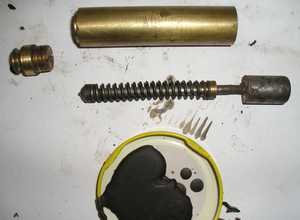
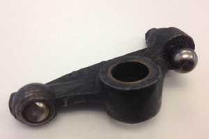
It was impossible to find out how it had been manufactured in the first place. I assumed that there had to be separation. So I cut off some material on the lathe. This way I found a threaded end plug and managed to disassemble the pieces. It contains a spring loaded piston, which is sealed by some sort of packing material. The action is performed by paraffin which changes physical state at 54°C with expansion. So far – simple see the picture aside (looks bend but it isn’t -just the photo thing).
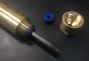
To rework it, I got a modern polyurethane piston seal 5x11x5mm, manufactured a threaded cap for one end which holds the piston seal in a new recess in the old part. On the other side I turned a brass ring on the plug to solder it onto the plug, so that is was similar to before machining, except that the parts have wrench faces to close and open them. That plug is sealed with a high pressure copper ring. Then I pulled out the piston as far as possible and blocked it there and heated up the actuator. Now I filled in there new paraffin with a melting point of 56°C. As much as possible so that it gets liquified. Once it just starts to solidify again it shrinks a bit. Then I closed everything with the plug, carefully avoiding air bubbles. To do that I heated just the surface of the paraffin puddle a bit.
Once the piston blocking has been removed I heated up everything. It felt there was just a bit too much paraffin inside, so I opened up the plug just a tiny bit to relieve the pressure. After a couple of cycles hot-cold etc. it works like a charm. It starts actuation at 65 °C up until 80°C when it travels some 21mm. A bit proud of myself…
If you do have the same problem: Unthread the cap with some very sharp pliers (grab it on the last 5mm). Disassemble it and place the PU seal right were the old seal was. If you do need paraffin? I still have more than enough, you’ll get it: send me a photo of your part and I’ll send it for free (only postage).
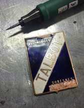
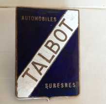
The original badge of the radiator had some chipped off emaille. The emaille is kind of opaque. I want to repair just the bits and leave the original part as is. After a proper cleaning of the edges I precoloured the copper and mixed a matching very thin epoxy with very little colour particles. The remaining air in the resin need to be removed in an exicator. This took 6 hours until it’s 100% clear. Then I mixed in the hardener, filled the remaining spots, hardened it at 120°C, sanded it flush up to 1000grid, and hand polished it. This looks pretty close with the new renickeling.
Ignition (3-6/2015)
The distributor from Delco was there. I found most of the bits and pieces in boxes. The shaft is running nice without play, so the housing just needed cleaning and painting. The centrifugal weights were cleaned, the springs checked. As with the Mercedes I am very much convinced that transistor ignition is a compromise one can accept in a vintage car. The motor runs so much more hassle free, and one doesn’t see it. Fortunately Ignitor has a system RR162 which fits with a clip on the shaft and right in the delco distributor. This was new to me: installing pieces without the necessity to rework something!
The sparc plugs were not easy to find. I finally sourced them from KLG. They do have the standard M4 thread contact. The original had some sort of conical contacts, to receive nice AC Delco sparc plug caps. I had one cap like that and searched forever to find more. I had to give it up, so made a silicone mold of the one left, and vacuum cast 6 new ones out of tinted epoxy resin. The commonly used PU resin are only good for 80°C, which seemed too low. Because the contact is different I turned brass contacts on the lathe with a tiny spring inside, so that they’ll clip on the sparc plugs as usual.
So all new sparc plug caps – fully hand made!
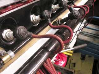
Next step was to restore the tube which holds the ignition cables. Usually they were made of bakelite or similar. The Talbot piece was out of painted wrapped paper. It had some dents and worn paper but mostly original. So I filled the holes with paper and resin and stabilized the worn paper also with resin. Then I used a fine brush and filled just the broke paint with nitrocelluse paint. After fine sanding with 1000 grid paper and polishing the tube is still 99% original, but does not look shabby.
The first ignition cables were still in the tube, leaving me with a protected sample to reproduce the cables. There are sort of red-brownish color textile knitted and painted cables. You can buy bright red textile wrapped ignition cable, which I tinted with medium dark walnut wood stain- I had it, so I used it.
Then I shellac-coated the cables with a cloth. Actually this looks amazing! No difference to the old cables.
Starter Motor (5/2015)
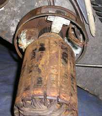
The starter motor was there but one solid piece. It took me quite a while to figure out how to disassemble the motor.
Interestingly the starter motor is separate from the dynamo, which is different from the smaller 2 and 2.5l cars which had a dynastart unit in front of the motor. I guess because Talbot took this motor from the DUS TL models.
The shaft did not move at all, 7 of 8 coal springs where just rust, and so on.
Once disassembled its simple:
Remove the rust on everything, sand the commutator, rewrap the stator coils, find new bearings, coals and springs and bendix springs (from a Ford A) and reassemble everything.
Runs like a charm! Simple? Took 5 weeks!
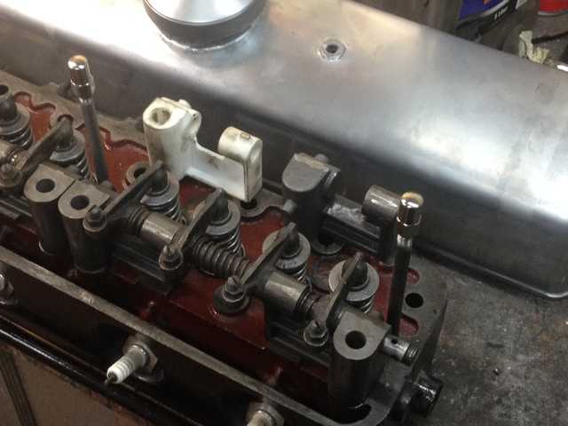
Valvetrain (2-12/2015)
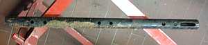
The camshaft went to Techniprofil. They want to regrind the cams which were very rusty. First I thought I had to rebuild the whole camshaft, which would have been expensive, but they were confident, that they would fix it. And they did:
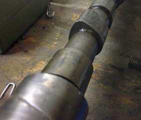
Old 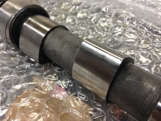
Reworked
I turned 4 new valve guides out of round cast iron stock an pressed them in the cylinder head. I heated up the head to 120°C and cooled down the guides to -20°C. With a special tube stub it took 3 careful whacks with a hammer and the guides are in place. As described earlier the valvetrain was partly missing. The valve rockers from the M67 could be reused, also some springs which hold them in place.
Once the cylinder head came back I decided tho use one whole new set of valvesprings. So I measured the springrate ansd dimensions and found proper very similar ones at Febrotec. On their website is a good search tool. Not expensive.
The shaft and support for the valve rockers is missing. These parts provide the lubrication. The oil is fed into the cylinder head from one end, through the last support, the rocker shaft, the next support back into the head. Then into the next support and so on. There are litte holes in the shaft to lubricate the rocker bearing then through the rockers into a spherical reception which holds a ball with one flat surface, providing the gap to the valve stem.
So I took all the measurements and redesigned these supports. To check the basic design I had it 3D printed and assembled everything preliminary. This was a good idea, because the design required minor alterations. Then I designed a cast model with extra for machining and shinkage during casting. I printed that model as well, and went to a local foundry where they recast the parts in grey iron.
Once these parts arrived, I machined all the surfaces, and drilled all bores. Now these parts were ready to be mounted back on the head, were the bores for the rocker shafts could be reamed, so that the bores are perfectly aligned.
The picture left shows the 3Dprinted part (upper left in white), the raw cast part (upper right), an the finshed ass’y below.
I still have to machine new shafts and get three new springs which hold the rockers in place.
The shaft for the rockers from a M67 was too short, so I had to make a new one. I bought 12mm round stock made to my desired length from Misumi (a good sorce for all kinds of technical things). It comes hardened, ground and hard chromed. It needed a thread at both ends and two plugs which I made out of a shortened bolt. The holes in the shaft had to be drilled with hard carbide drills, everything else is nonsense…
The balls in the rockers are worn and partly seized. To get them out of their seat I drilled a small hole from the back and pushed them out. That hole had to be welded afterwards. The balls are 9mm which I could not find. But Zündapp KS601 motorcyles have a similar 10mm ball. So I milled a slightly bigger sphere with a 10mm ballnose cuttter and used those balls which you can get from all kind of shops. The Zündapp guys also tried ceramic balls but that seems to space-age for me. Of course I replaced the old bronce bushings with new ones. This all assembled looks very promising.
The pushrods are ordered from CompCams.
Gearbox and clutch (1-4/2015)
I took apart the gearbox. Fortuneately everything was in pretty good shape. So I just replaced the bearings. Some outer parts are renickeled. The drive for the speedometer was only left in parts. Main problem was the spiral drive for the speedometer. You can get themin chorme easily, but originally they were only steel. I finally found some in stainless steel which was not polished. That looked exactly like the original. The ends were made new or reused and zink coated.
The gearbox is filled with thick gearbox grease. That stops the secondary shaft faster, making gear changes quicker. It worked well on my Citroen, so why not use ist here too?
I sent away the cluth disk to have it relined. The clutch assembly was just cleaned, but the disk was not even. So I set up a preliminary support grinder with an angle grinder on my lathe, and ground the surface. The setup looks horrible but worked actually very well. The dial did show just 0,003 mm out of plane :-).
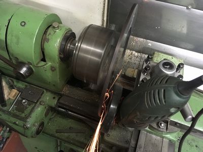
Grinding the clutch 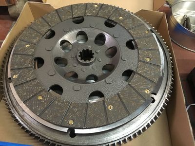
New lined clutch plate
Motor Block (1/2015-10/2017)
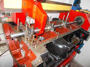
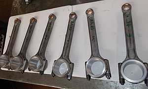
The block itself went to a professional shop (Buchheister & Oppelt in Ribesbüttel). Alle bearings had to be reworked as well as new pistons. First they had new central beerings made. Reground the crankshaft accordingy. Measured the bore in the block an redrilled that as well. The piston links needed also new white metal bearings. So they were recast and machined.
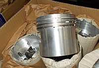
The pistons were not there so new pistons were machined from Mahle blanks by Wahl Pistons. The bores were drilled out and honed.
The pistons pins were also made new and fitted to the piston links. All that was assembled to determine the final height of the pistions. then the crankshaft, blancing weight and clutch has been balanced.
All this took more than 1 1/2 years to get all the parts machine and fit them.
I checked the oil pump, and just cleaned it as the tolerances were quite ok. Then oil pump, cylinder head and camshaft are assembled. I had the little pistons for the pushrods nitrided. They should not grow but they did. So I reground them so that they fit again.
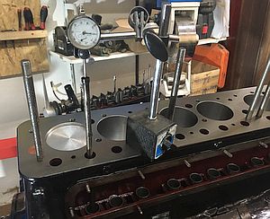
To get the timing of the camshaft right I used a dial to find the start of the valve lifting exacly. That worked well as all open and close points are marked on the flywheel.
Then I assembled the oil pan and all covers to finish it up with the cylinder head. The studs here are strange M11. I machined partly new studs from CrMo42 and reworked new nuts from M10 10.9 nuts. The thread pitch is the same, so that worked well. Once I finally put the head on I tapped it down with a rubber hammer, which caused again rust particles falling out of the head.
I did clean it beforehand numerous times, so after some swearing, I cleaned out the rest in the cylinders throgh the spark plug hole (!) with an endoscope. Painful work. But then once turning the motor the pistons clearly hit something on the top. In fact the gasket is from a K74, so has a 74mm bore, mine has pistons 75mm bore. The pistons are not flush but protrude 0,5mm out of the sealing surface. Should not be a problem, but two pistons barely just hit that gasket. So I send away the gasket to have a new one made… Shi:-/$~#
With the new gasket I could finish the motor. The pushrod were manufactured from mopar parts as the seats in the rockers and on the camshaft are imperial sizes.
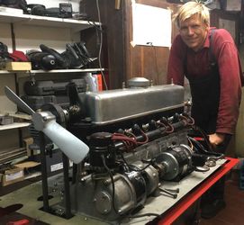
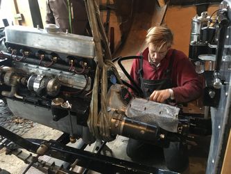
Together with the mounted gearbox it is too heavy for a motor crane, so my neighbour helped me with his traktor. Getting it in the chassis was not easy as everything is pretty tight between the rigid motor mounts.
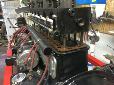
The copper tubes for vacuum and gasoline were next. Here I had to change the routing of the gasoline tube, which originally was close to the exhaust manifold, but todays gasoline tends to bubble, so I routed it below and outbound to keep it cool.
Nearly finished. I still have to sort out all nozzles for the carburettor. At least this is my excuse for not starting the motor right now.
Central lubrication (11/2015)
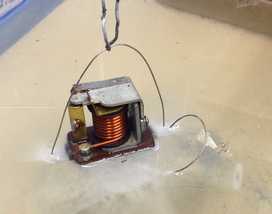
The P75 came out with new improvent: A central lubrication system from Tecalemit. My car had the pump, but all parts inside were missing. In consists out of a reservoir, some check valves, a small piston which pumps the oil from the reservoir. That piston is actuated with a pulling knob from the dashboard. Once pulled, it’s pushed down from a bigger piston which is actuated with vacuum from the intake. I know it’s a mess due to dripping oil, but this is how it was and it is part of the history. So it will all be back in place and not be replaced with grease nipples. You do not install xenon headlights either, just because its better -right?